OUTLINE:
Easy to Grasp: Wiring Schematic for Light Switch
 85
85To understand the wiring schematic for light switch better, it is important to learn some basic circuit knowledge. A complete circuit usually consists of a power source (such as electricity from a battery or mains outlet), a load (in this case, a light), a wire, and a control device (i.e. a switch). The current starts from the power supply, flows through the wire to the load, makes the load work, and then returns to the power supply through the wire, forming a closed loop. As for the wiring of the light switch, it mainly involves three wires: Live Wire, Neutral Wire and Switch Wire. It should be noted that in modern home circuits, the neutral line is usually not directly connected to the switch box, but directly connected to the lamp. The switch is mainly responsible for controlling the on-off of the fire line. The magnitude and direction of this current will change periodically over time. The electric lamp, as a load, works based on the heat generated when the current passes through the filament, making the filament glow.
Basic concepts and principles of wiring schematic for light switch
Basic concepts
A wiring schematic, simply, is a diagram showing how the various components in a circuit are connected. For wiring schematic for light switch in specific, it mainly shows the connection between the switch, the lamp and the power supply.
And the light switch is a normal electrical part frequently used in our home or company, whose main role is to control the on-off of the circuit, so as to realize the opening and closing of the light.
Usually, in a wiring schematic for light switch, you will see the following aspects.
|
Basic components in a circuit |
|
|---|---|
|
Component |
Usage |
|
Live wire |
A wire that carries current, usually with a voltage. |
|
Neutral wire |
A wire in which current is returned, usually without voltage. |
|
Ground wire (sometimes not directly involved in switch wiring) |
It is used for safe grounding to prevent electrical leakage. |
|
Switch |
A device that controls the interruption of electrical flow. |
|
Lamp (Load) |
A device that consumes electrical energy, in this case refers to a light bulb or lamp group. |
Working principle
There is usually one or more contacts inside the switch that open or close when the switch is operated, thereby shutting off or allowing current to pass through. In the light switch, we usually close the contact to make the current flow to the lamp and turn on the light; Turn off the current by opening the contact, turn off the light.
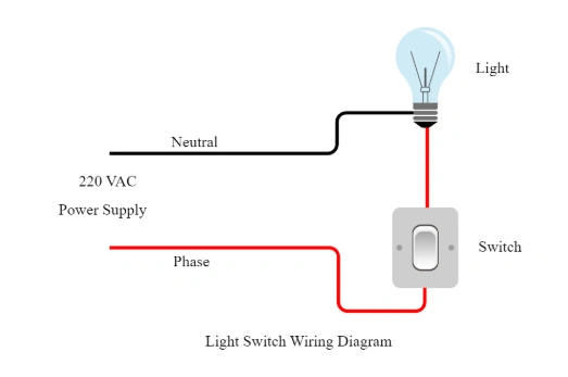
As for the basic principle of single switch controlling one light, the live wire of the power supply (generally a red wire) is connected to one end of the switch, the other end of the switch is connected to one end of the light through the wire, and the other end of the light is connected to the neutral wire of the power supply (generally a blue wire). When the switch is closed, the current of the live line reaches the lamp through the switch, and then forms a loop through the neutral line, and the electric light is on; When the switch is off, the circuit is cut off and the light goes out.
While for the principle of dual switch control of one light, also called two places control, in this case, two dual switches are needed. The power live wire is connected to the common end (COM) of the first double switch, the other two terminals (L1 and L2) of the first double switch are connected to the L1 and L2 terminal of the second double switch with two wires respectively, the common end (COM) of the second double switch is connected to one end of the light, and the other end of the light is connected to the power neutral wire. By operating two dual switches at different positions, the connection mode of the circuit can be changed to achieve the control of the same light on and off in two places.
Different types of wiring schematic for light switch
Wiring schematic for light switch can be divided into different types according to its control mode and application.
1. Single-control switch
The single control switch is the most common type, which can only control the light on and off in one position.
Single-control switches usually have three terminals: L (live wire into the line), L1 (live wire out, connected to the lamp) and N (neutral line, but the neutral line in modern home circuits is usually not directly connected to the switch box, but directly connected to the lamp).
The wiring diagram is very intuitive: the live wire of the power supply (generally represented by a red wire) first accesses a wiring terminal of the switch, and then leads a wire from the other wiring terminal of the switch to connect to one end of the lamp; The neutral wire of the power supply (generally represented by a blue wire) is directly connected to the other end of the lamp. In this way, when the switch is closed, the current from the live line through the switch, the lamp, and then through the neutral line back to the power supply, forming a closed loop, the electric light on; When the switch is off, the circuit breaks and the light goes out.
The single control switch is suitable for the occasions that only need to control the light in one position, such as ordinary lighting fixtures in bedrooms or bathrooms. It has the advantages of simple structure, convenient installation and low cost.
2. Dual control switch
Dual control switch allows the control of the same light in two different positions, usually used in stairs and corridors.
Dual control switches usually have three terminals (some brands or models may have four, but the principle is the same) : COM (common end), L1 (first control end) and L2 (second control end).
When wiring, it is necessary to use two control wires to connect the two dual-control switches. The L1 of one switch is connected to the L2 of the other switch, and the COM end of the two switches is connected to the firewire and the firewire end of the lamp respectively.
When the switch is operated in one position, the on-off state of the control line will be changed, thus controlling the opening and closing of the lamp. When operating in another position, the state of the control line will also be changed to achieve the control of the lamp.
3. Three-control and multi-control switch
Three-control and multi-control switches allow the same light to be controlled in three or more locations and are often used in large rooms or complex layouts.
The multi-control switch is a further extension of the dual-control switch, which can control the same light in three or more positions. The implementation of multi-control function usually requires the use of multiple dual-control switches and a mid-way switch (also called multi-control switch). The wiring method is more complicated, and the route direction needs to be carefully planned. To control a light in three positions, for example, first connect the power live wire to the L terminal of the first dual control switch, and lead two wires from the L1 and L2 terminals of the switch to connect to the two corresponding terminals of the midway switch. The other two terminals of the midway switch then lead two wires to the L1 and L2 terminals of the second double-controlled switch. Finally, the lead wire from the L terminal of the second double control switch is connected to one end of the lamp, and the other end of the lamp is connected to the neutral line. In this way, the lighting can be easily controlled at three different locations. Multi-control switches are often used in large conference rooms, corridors and other places that need to control lighting in multiple locations.
4. Intelligent switch
With the development of smart homes, smart switches have gradually become the mainstream. The smart switch can be controlled remotely through mobile APP, voice assistant, etc., and has functions such as timing and scene linkage.
The wiring mode of the smart switch varies according to the type. Common Wi-Fi smart switches generally need to be connected to the home wireless network first. When wiring, the power live wire is connected to the live wire input end of the intelligent switch, and the leading wire from the live wire output end is connected to one end of the lamp, and the other end of the lamp is connected to the neutral wire. At the same time, the smart switch also needs to be connected to the home router and configured and controlled through the mobile phone APP. The Bluetooth smart switch communicates with a mobile phone or other Bluetooth device through the Bluetooth protocol. The wiring method is similar to the Wi-Fi smart switch, but relies on Bluetooth technology for connection and control. There is also Zigbee intelligent switch, which uses Zigbee wireless communication standard, has the characteristics of low power consumption, flexible networking, etc., and the wiring method is roughly the same, but it needs to cooperate with Zigbee gateway to achieve remote communication and control with mobile phones and other devices.
Installation with wiring schematic for light switch
Before starting any electrical work, be sure to turn off the power switch of the circuit and use the pen to confirm whether the circuit is completely powered off.
Then, prepare tools and materials for the following assembly, such as screwdriver (including flat and cross), electrical tape, terminal or crimper, new light switch, electric pen (to detect whether the circuit is live).
According to wiring schematic for light switch, connect the wires on the wall with the corresponding terminals of the new switch. Usually, the live wire (usually red or black) accesses the "L" or "COM" terminal of the switch, the neutral wire (usually blue or white) usually does not access the switch (directly connected to the light fixture), and the control wire (connected to the live wire end of the light fixture) accesses the switch's "L1" or "L2" terminal. Then wrap the exposed wires on each post with electrical tape to ensure safety.
Maintenance with wiring schematic for light switch
After successful installation, maintenance of the circuit is also important. Periodically check the appearance of the switch and whether the terminal is damaged or loose. If the switch panel is cracked, the terminal is loose, or the wire is exposed, replace or repair it immediately. Moreover, it is not suggested to use a damp cloth or corrosive detergent to clean the switch for there being damage to the panel or a possibility leading to short circuit.
Of course, if you find that the switch does not work properly or there is a safety hazard, you should immediately replace the old one according to the wiring schematic for light switch. When replacing the switch, select a switch of the same model or compatible model as the original switch to ensure that the cable connection is correct and the function is normal.
FAQ for wiring schematic for light switch
After having a look at the above content, you may have some understanding of wiring schematic for light switch. So here are some frequently asked questions and see if they can solve yours as well.
My switch has three terminals, but only two wires?
A: This may be because your switch is one of three switches, or there is a spare terminal in the original design. Check switch model and circuit design to ensure correct wiring.
What should I do if the light is not on after the dual control switch is connected?
A: First check whether the power supply has been restored. Then, use the test pen to check whether each terminal is powered. If the problem persists, it may be a poor wire connection or a damaged switch, please check one by one.
What if the bulb flashes frequently after changing the switch?
A: This can be caused by poor contact or unstable voltage. Check that the switch is securely wired, or consider consulting an electrician to check the circuit.
Final Verdict
By mastering the knowledge of wiring schematic for light switch, you can better understand the working principle of the home circuit and improve the convenience and safety of home life. Hope this article can provide you with valuable reference and help!
Disclaimer: The views and opinions expressed by individual authors or forum participants on this website do not represent the views and opinions of Chipsmall, nor do they represent Chipsmall's official policy.

share this blog to: